3 hours
After some more research, I realized that it would make way more sense to use an I2C-based OLED panel rather than the 15-pin 14-segment LED display I found. This even makes sense from a cost perspective, since removing the need for a lot of GPIO pins allows for using a cheaper board than the Arduino.
For the OLED itself, I found one from DFRobot that is more of a breakout, which means that I can just use throughholes and a pin header to connect it to my PCB.
For the microcontroller, since I no longer needed to worry about a GPIO requirement, I’m now using an RP2040 Seeed Studio which is a way smaller board that also costs quite a bit less. This is still mounted underneath the PCB, but it will work a lot better than the Arduino with the different sizing.
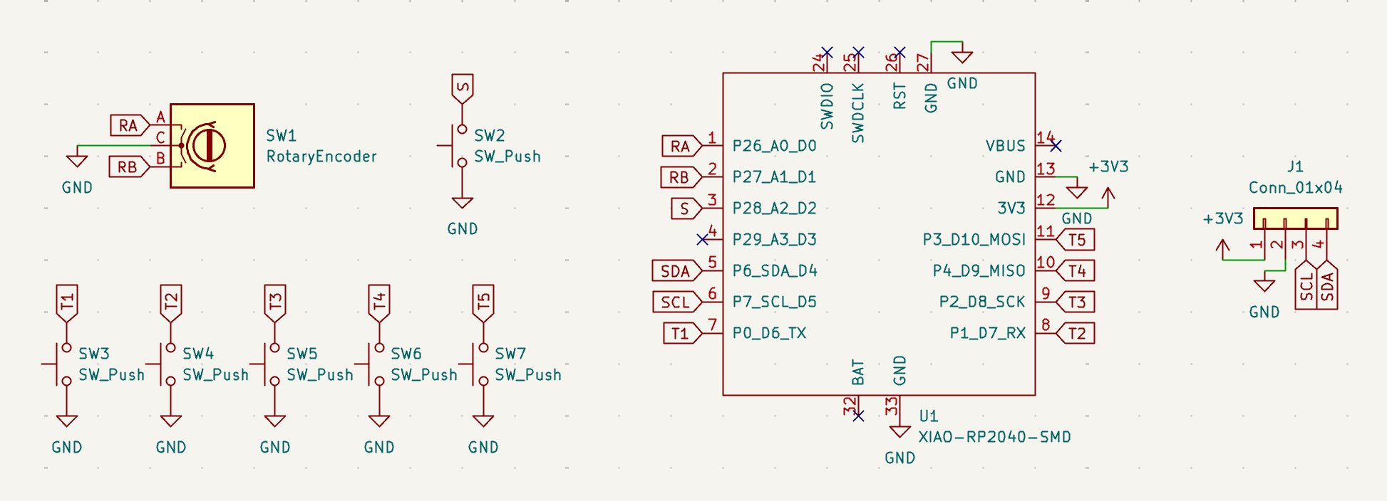
Of course, changing these components means that I had to redo the entire schematic and PCB. The schematic was pretty simple, since the only changes I made were to simplify the components.
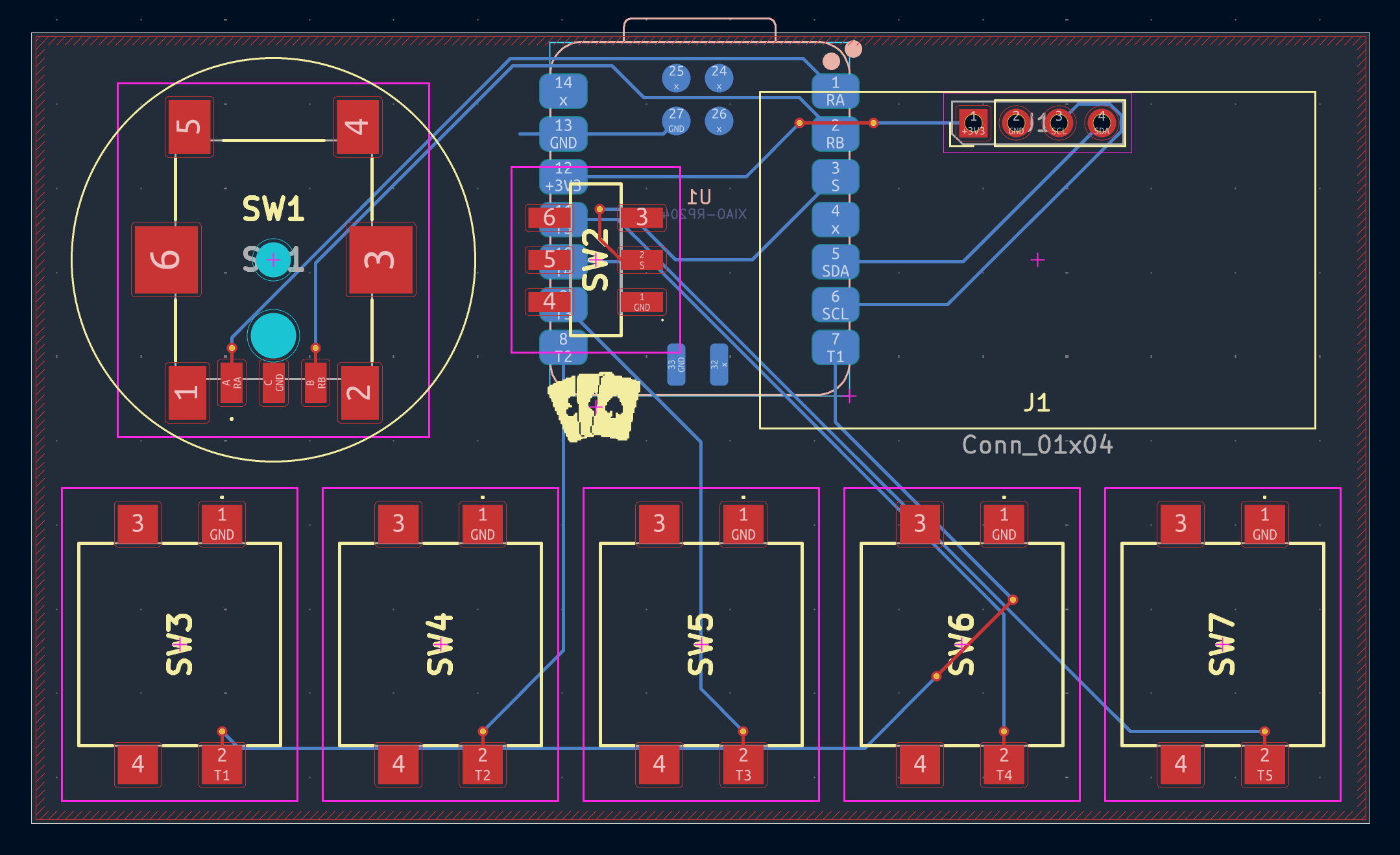
Then, I rerouted the PCB with the simplified wiring. I decided to go back to a 2-layer PCB, and tried to try to minimize the amount of traces on the front of the board. The OLED is much wider than the 14-segment LED display, which means that the rotary encoder and switch were moved to the left side, but I think it works pretty well.