3 hours
I designed the schematic and routed the PCB for my controller.
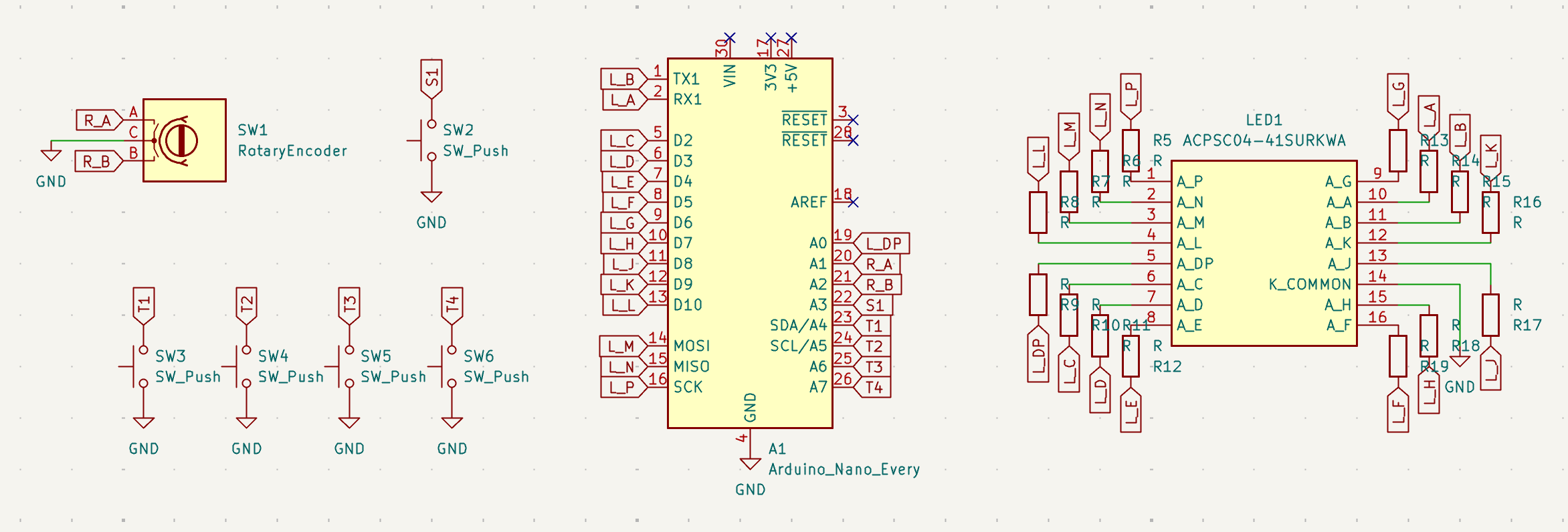
Once I figured out which components I wanted to use, creating the schematic ended up going pretty smoothly, since using the parts isn’t that complicated. The only real interesting part to the schematic was just trying to have everything laid out in a clear, readable way which was a bit tricky given how dense the wiring around the 14-segment display is.
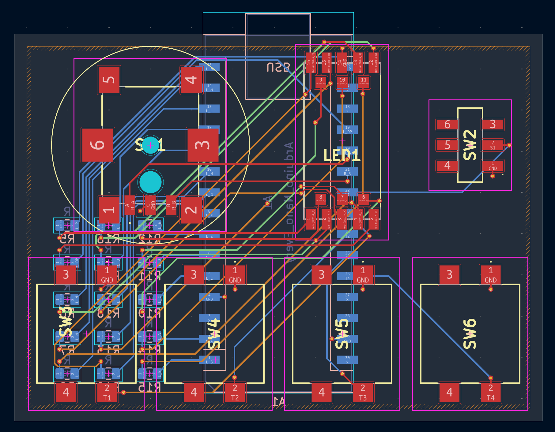
After that, I proceeded to routing the PCB. I decided to go with a 4-layer layout to make the wiring a bit less messy (also since JLCPCB doesn’t charge extra for it), and proceeded adding the components and laying out the entire thing. Since I needed a bunch of resistors for the display, I put those on the back with the Arduino to make the board a bit cleaner, since the front then only has components that the user can directly interact with.
Generally, creating the PCB went pretty smoothly, though it took a bit of extra effort since basically all of the parts I used aren’t in the standard KiCad library and thus needed to be added as footprints and models (or even symbols in the case of the display). I also made some small changes to make figuring out sizing a bit easier, like adding a circle around the encoder to mark out where the knob would be spatially.
A lot of time was also spent on just making sure that everything is positioned in a nice way.